Contact Us

REMOTE, WIRELESS & SENSOR-TRIGGERED WARNING

Industrial Warning Signals for Remote, Sensor & External Control

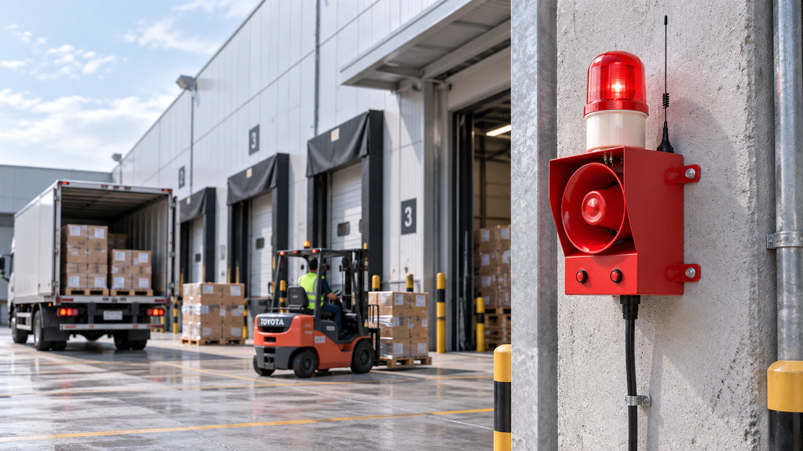
Start with what should trigger the warning—an operator, detection event, machine signal or connected system. Then confirm how that trigger reaches the warning point.

What Should Cause the Warning to Start?

Identify the trigger source first, then choose the control approach that matches it.

STEP 2 — CHOOSE A STARTING CONTROL APPROACH

How Should the Trigger Reach the Warning Point?

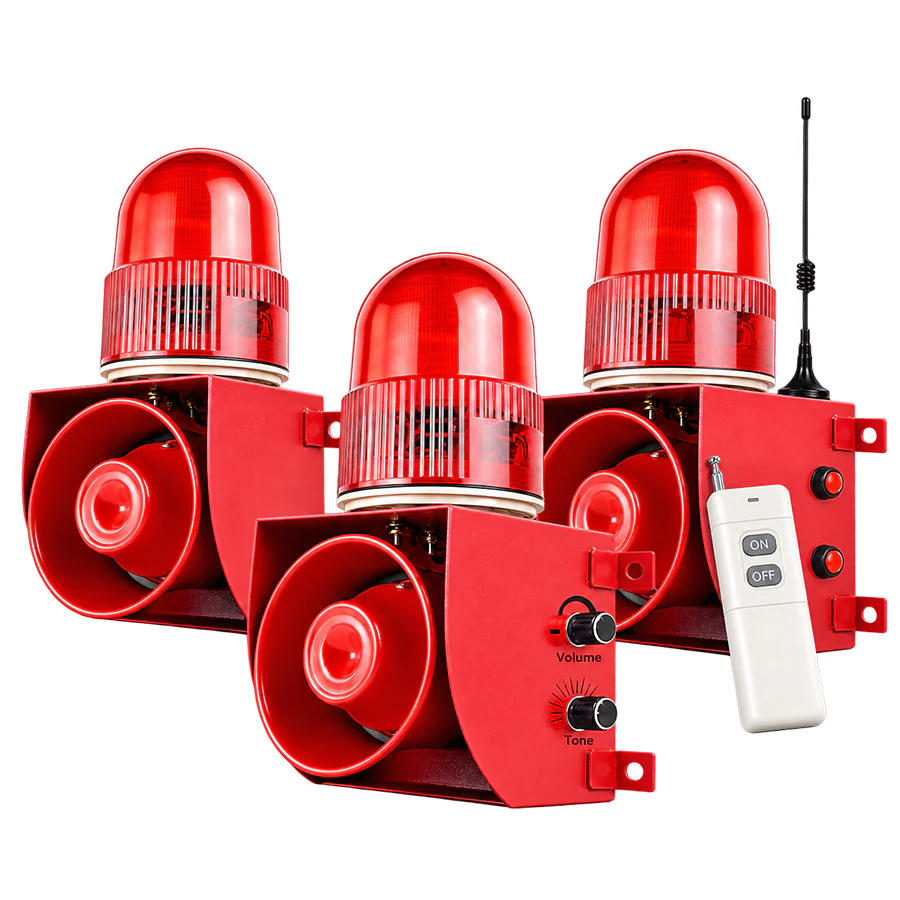
REMOTE OPERATOR ACTIVATION

Control the warning from another working position.

Use this route when the operator and installed warning point are separated.
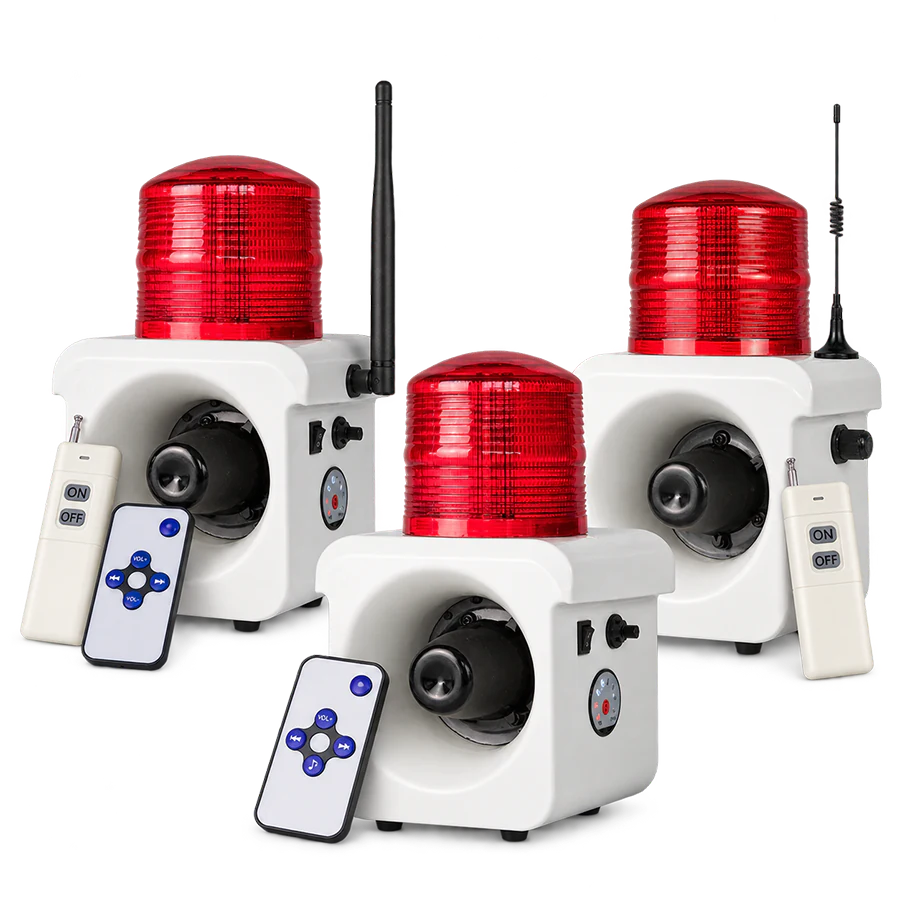
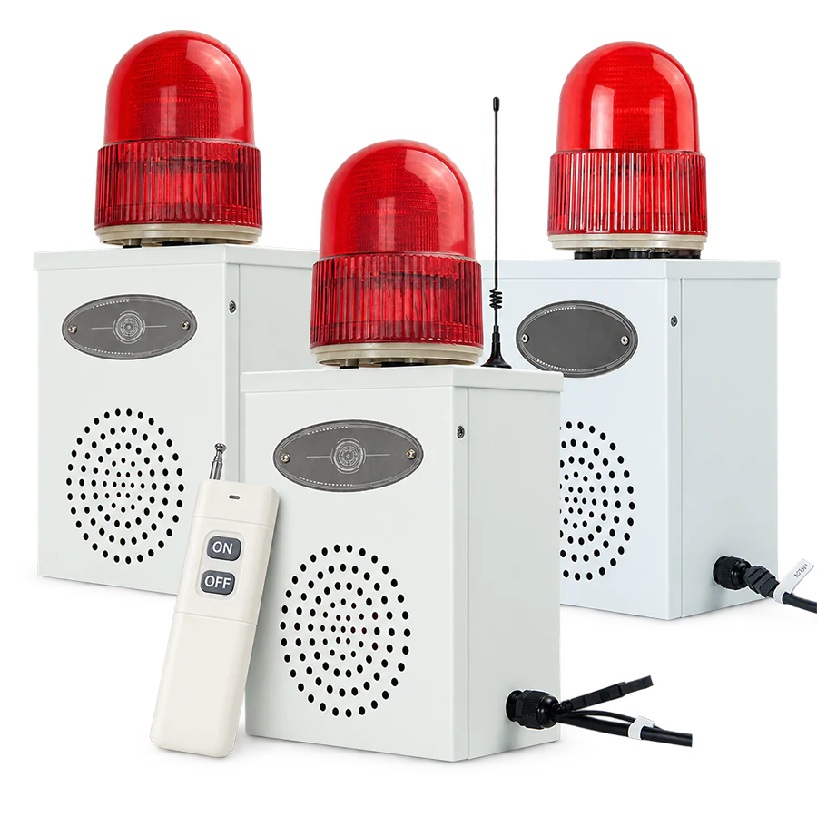
ALX-300 Series Selected remote-control configurations
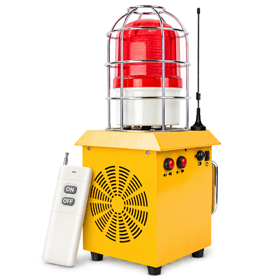
ALX-610-RC Portable rechargeable remote operation
NEXT QUESTION

Where are the operator and warning point, and what site conditions separate them?

Validate the Control Path
AUTOMATIC DETECTION

Start the warning after a defined detection event.

Use this route when warning operation should not depend on an operator command.

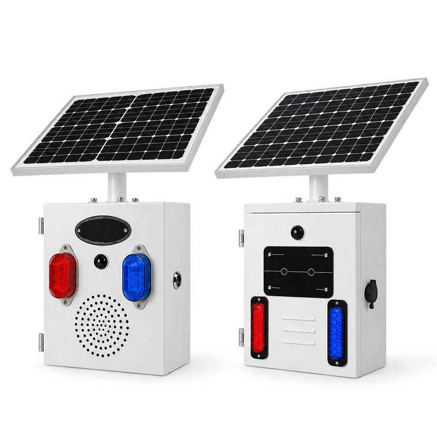
ALX-700 Series Sensor-triggered audible + visual warning
ALX-300 Series Selected detection-oriented configurations
NEXT QUESTION

What needs to be detected and where should the sensing point be located?

Validate the Detection Path

EXTERNAL SIGNAL CONTROL

Let another device provide the trigger.

Use this route when a machine, relay, switch or controller starts the warning.

ALX-300 Series Selected signal-input configurations
ALX-500 Series Selected external-control configurations
NEXT QUESTION

What device supplies the signal and what interface must the alarm accept?

Validate the Signal Path

CONNECTED / COMMUNICATION CONTROL

Operate the warning through a connected system.

Use this route when commands come from a controller, network or industrial system.

ALX-100 Series Selected linked & communication configurations
ALX-500 Series Selected industrial-control configurations
NEXT QUESTION

What communication method and system interface does the project require?

Validate Connected Control

Validate the Control Path and Warning Point

Confirm the interface, location, power and output before moving to product-level selection.

CONTROL PATH

What Must Be Confirmed for the Selected Trigger?

01
Remote Command

Confirm operator location, warning-point location and relevant obstacles or site conditions.

02
Automatic Detection

Confirm what must be detected, where sensing occurs and the applicable operating conditions.

03
External Electrical Signal

Confirm which device supplies the signal and the interface required by the selected alarm.

04
Network or Industrial Communication

Confirm the required communication method, controller and system interface.

Remote control does not mean wireless power. The warning point may still require a conventional power connection.

RS-485 is an industrial communication method, not wireless control. Treat remote control, signal input and communication as separate requirements.

Match the Control Requirement to a Product Route

Use the confirmed trigger, interface, power and warning output to continue with product-level comparison.

REMOTE OPERATOR ACTIVATION

Selected Remote-Control Configurations

Operator-Controlled Warning

Choose this route when an operator needs to control the warning from a separate working position.

Products to Review

Selected ALX-100, ALX-300 and ALX-500 configurations, plus ALX-610-RC for portable remote operation.

AUTOMATIC DETECTION

Sensor-Triggered Configurations

Automatic Warning Activation

Choose this route when the warning should start automatically after a defined detection event.

Products to Review

ALX-700 and selected ALX-100, ALX-300 and ALX-500 detection-oriented configurations.

EXTERNAL SIGNAL CONTROL

Signal-Input & Linked Configurations

Equipment & External-Control Warning

Choose this route when a machine, relay, switch or controller supplies the trigger.

Products to Review

Selected ALX-100, ALX-200, ALX-300 and ALX-500 signal-input or linked-control configurations.

NETWORK & INDUSTRIAL COMMUNICATION

Connected Control Configurations

Network · Wi-Fi · Industrial Communication

Choose this route when warning operation forms part of a network or industrial control system.

Products to Review

Selected ALX-100 communication configurations and ALX-500-485 for RS-485 / Modbus-RTU applications.

Remote distance, sensing method, electrical input, communication settings and power requirements are configuration-specific. Confirm the selected model before ordering.

Frequently Asked Questions

Yes. A controller reference, wiring drawing or control diagram can help clarify the required signal, communication and installation conditions.

PRODUCT RECOMMENDATION

Tell Us How the Warning Needs to Be Triggered

Share what should start the warning, where the control or detection point is located and what needs to happen at the warning point. We can review the suitable control and product configuration before quotation.

  • Tell us whether the warning starts from an operator command, detection event, external signal or connected control system.
  • Add the control distance, power source and warning output if they are already known.
  • Upload a control diagram, site photo or existing product reference when it helps explain the requirement.

Control method and power source are separate selection factors. A remotely controlled alarm may still require a conventional power connection.

No files selected

PDF, JPG, JPEG, PNG, DOC or DOCX. Maximum 3 files, 10 MB each and 15 MB total.

Add Control & Technical Details (Optional)

Required fields are marked with an asterisk.